Overview
The UsdLux schema domain contains schemas for working with lights and light-related behaviors (e.g. shadows, light filters, etc.). UsdLux is designed to provide representations of lighting used in a typical 3D graphics setting in an efficient and portable way.
UsdLux Schemas and Concepts
UsdLux includes several schemas that provide the following features:
Endow light capabilities
Represent boundable lights (e.g. SphereLight)
Represent non-boundable lights (e.g. DistantLight)
Enable light-shaping and shadowing capabilities
Represent light filters
Each of these is described in the following sections.
Endowing Light Capabilities
The LightAPI schema imparts “light capabilities” to the prim it is applied to, so the prim can be treated as “being a light”. The schema has attributes that lights are expected to have (and renderers will use for performing lighting calculations), such as light intensity, color, exposure, and other features. These attributes are described in more detail in Understanding Light Contributions.
Representing Boundable Lights
OpenUSD provides several typed schemas that represent boundable lights. Boundable lights are lights that have scene bounds and positional information, used in lighting calculations. For example, a SphereLight is a boundable light, with a position and radius. Boundable lights derive from BoundableLightBase, which in turn has the LightAPI schema applied.
BoundableLightBase derives from Xformable, so that all boundable lights can be transformed like any Xformable prim (note that some renderers might not process non-uniform scaling of lights), using the xformOp and xformOpOrder attributes. The following example translates and rotates a RectLight.
def RectLight "Light"
{
    ...

    # Position light as needed
    float3 xformOp:rotateXYZ = (90, 0, 0)
    double3 xformOp:translate = (0, 0, 2)
    uniform token[] xformOpOrder = ["xformOp:translate", "xformOp:rotateXYZ"]
}
The boundable light schemas OpenUSD provides are:
The set of boundable (and non-boundable) lights that UsdLux provides are also referred to as “intrinsic” lights.
OpenUSD also provides the MeshLightAPI which can be applied to a Mesh prim to create a boundable mesh light. See Mesh Lights for more examples of using mesh lights.
Similarly, OpenUSD provides the VolumeLightAPI to create boundable volume lights from Volume prims.
Representing Non-boundable Lights
OpenUSD provides several typed schemas that represent non-boundable lights. Non-boundable lights do not have scene bounds and emit light throughout the entire scene. An example of a non-boundable light is a DistantLight that is treated as being arbitrarily far from the scene in order to behave like sunlight. Non-boundable lights derive from NonboundableLightBase which in turn has the LightAPI schema applied.
NonBoundableLightBase derives from Xformable (like BoundableLightBase), so Non-boundable lights can be transformed using xformOp and xformOpOrder attributes, however lighting calculations will ignore any translations of non-boundable lights.
The non-boundable light schemas OpenUSD provides are:
Enabling Light-shaping and Shadowing Capabilities
The ShapingAPI schema adds light emission shaping settings, such as light focus, light cone, and IES profiles settings. Use this schema for situations where you need control over the emission shape, such as making a light behave like a spotlight. See Light Shaping for more details and example of using ShapingAPI.
The ShadowAPI schema adds shadow settings, such as shadow tinting and shadow falloff. Use this schema when you need finer-grain artistic control over how shadows are rendered. The ShadowAPI attributes are “non-physical” controls, meaning they ignore certain laws of physics in order to apply the shadow settings. See Shadows for more details and examples of using ShadowAPI.
Representing Filters on Lights
The LightFilter schema describes a filter that modifies the effect of a light, for example adding a stencil or color gel effect. Note that LightFilter is used as a base schema for other light filters to inherit from – UsdLux does not provide specific light filters (beyond PluginLightFilter which is a special-purpose filter schema).
Lights refer to filters via one or more light:filters relationships so that filters may be shared across multiple lights if needed. The following example adds relationships for two (mocked) light filters to a DiskLight.
def DiskLight "Light1"
{
    color3f inputs:color = (0.2, 0.4, 0.8)
    float inputs:exposure = 3
    float inputs:intensity = 100
    float inputs:radius = 1
    append rel light:filters = [
         </World/Filters/BarnDoorEffectFilter>,
         </World/Filters/YellowGelFilter>,
    ]
}
Light filters can also be linked to geometry, to control which geometry the
filter affects. This linking is done by using a filterLink
collection on the
LightFilter. The following example configures the (mocked) MyFilter light
filter to only apply its filter effect on prims at </World/BuildingA>.
def MyFilter "MyFilter"
{
    uniform bool collection:filterLink:includeRoot = 0
    prepend rel collection:filterLink:includes = </World/BuildingA>
    # ... other filter settings as needed ...
}
Light Units
Most renderers consuming OpenUSD today are RGB renderers, rather than spectral. The main quantity in an RGB renderer is neither radiance nor luminance, but “integrated radiance” or “tristimulus weight”. For brevity, the term emission will be used in the documentation to mean “emitted spectral radiance” or “emitted integrated radiance/tristimulus weight”, as appropriate.
In OpenUSD, a light with default brightness (intensity of 1) and color (white) should be considered to have a luminance of 1 nit (cd∕m²), and its emitted spectral radiance distribution can be computed by appropriate normalization.
Understanding Light Contributions
UsdLux presumes a physically-based lighting model where falloff with distance is a consequence of reduced visible solid angle. Environments that do not measure the visible solid angle are expected to provide an approximation, such as inverse-square falloff.
Renderers can use the various lighting-calculation attributes of the LightAPI schema to determine the complete contribution from a light. The basic contributions from each attribute are as follows.
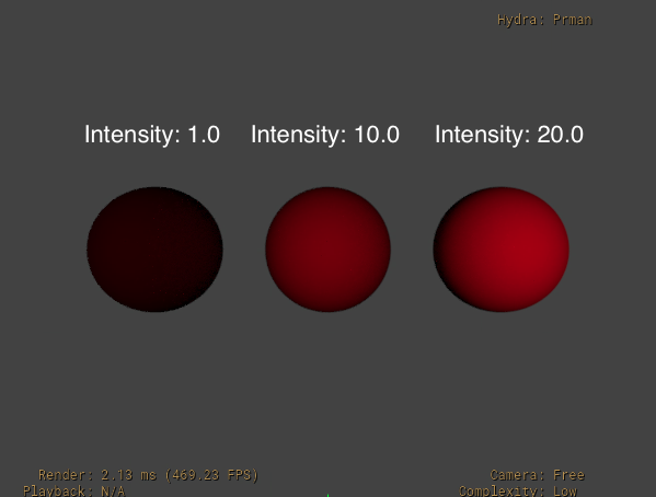
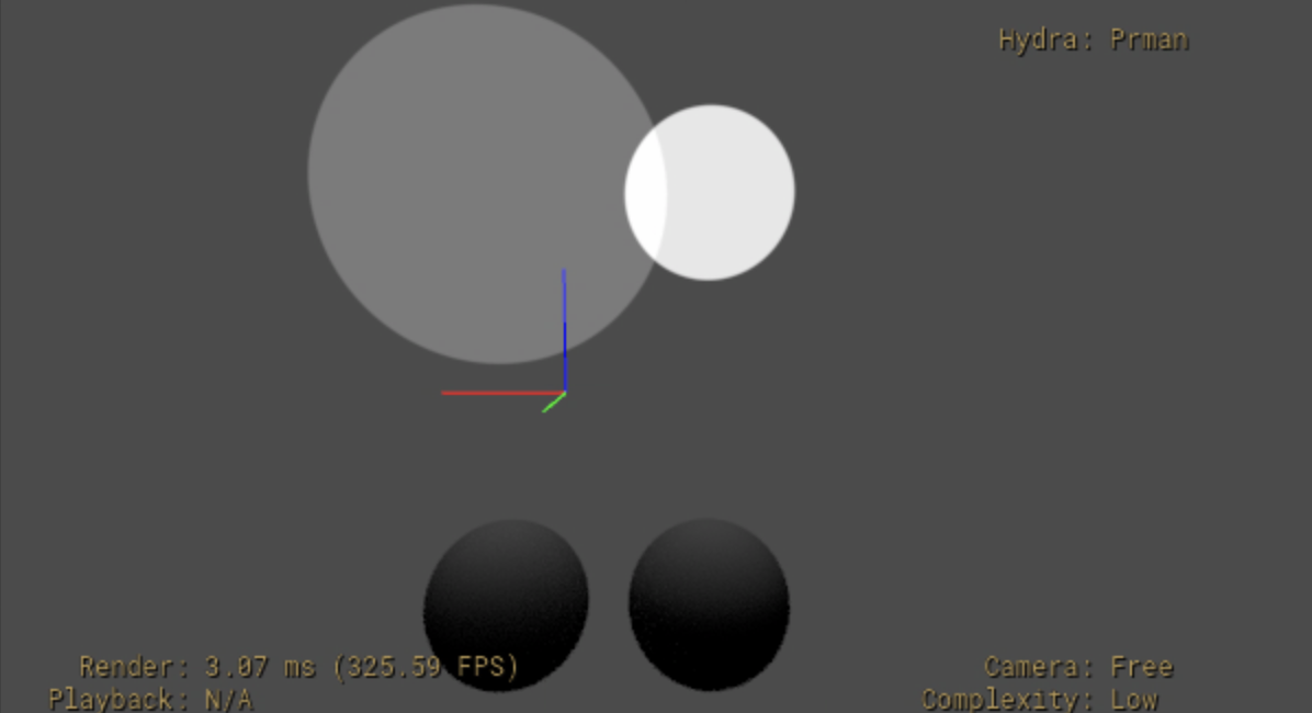
intensity scales the brightness of the light linearly, using physical falloff. The following example uses three lights with intensity values at 1.0, 10.0, and 20.0.
#usda 1.0
(
    upAxis = "Y"
)

def Scope "Lights"
{
    def RectLight "LightIntensity1"
    {
        uniform bool collection:lightLink:includeRoot = 0
        rel collection:lightLink:includes = [
            </TestSpheres/Sphere1>
        ]

        color3f inputs:color = (1, 0, 0)
        float inputs:intensity = 1.0
        double3 xformOp:translate = (-2.5, 5, 3)
        uniform token[] xformOpOrder = ["xformOp:translate"]
    }
    def RectLight "LightIntensity2"
    {
        uniform bool collection:lightLink:includeRoot = 0
        rel collection:lightLink:includes = [
            </TestSpheres/Sphere2>
        ]

        color3f inputs:color = (1, 0, 0)
        float inputs:intensity = 10.0
        double3 xformOp:translate = (0, 5, 3)
        uniform token[] xformOpOrder = ["xformOp:translate"]
    }
    def RectLight "LightIntensity3"
    {
        uniform bool collection:lightLink:includeRoot = 0
        rel collection:lightLink:includes = [
            </TestSpheres/Sphere3>
        ]

        color3f inputs:color = (1, 0, 0)
        float inputs:intensity = 20.0
        double3 xformOp:translate = (2.5, 5, 3)
        uniform token[] xformOpOrder = ["xformOp:translate"]
    }
}

def Xform "TestSpheres"
{
    def Sphere "Sphere1"
    {
        color3f[] primvars:displayColor = [(1, 1, 1)] (
            interpolation = "constant"
        )
        double3 xformOp:translate = (-2.5, 5, -2)
        uniform token[] xformOpOrder = ["xformOp:translate"]
    }

    def Sphere "Sphere2"
    {
        color3f[] primvars:displayColor = [(1, 1, 1)] (
            interpolation = "constant"
        )
        double3 xformOp:translate = (0, 5, -2)
        uniform token[] xformOpOrder = ["xformOp:translate"]
    }

    def Sphere "Sphere3"
    {
        color3f[] primvars:displayColor = [(1, 1, 1)] (
            interpolation = "constant"
        )
        double3 xformOp:translate = (2.5, 5, -2)
        uniform token[] xformOpOrder = ["xformOp:translate"]
    }
}
See the documentation for intensity for the formula for how intensity is applied in lighting computations.
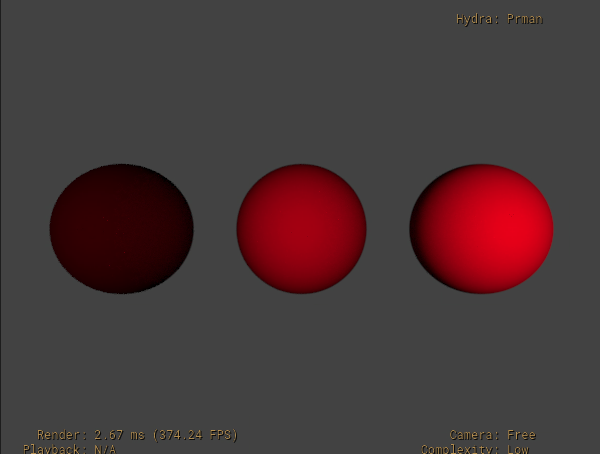
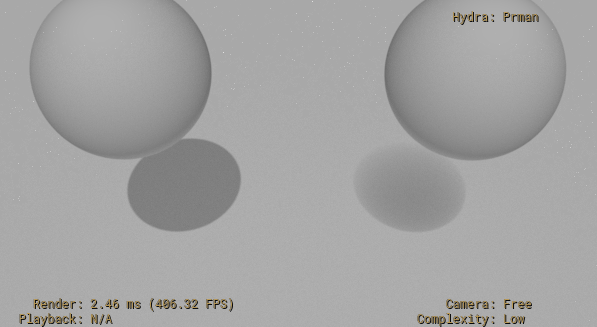
exposure scales the light brightness exponentially as a power of 2. The result is multipled against the light’s intensity. Increasing exposure by 1 will typically double the energy emitted by the light source. The following image is the same layer used previously (as an example of intensity values), but with each light getting an exposure value of 1.0.
See the documentation for exposure for the formula for how exposure is applied in lighting computations.
specular and diffuse values are used as a multiplier to a material’s specular and diffuse components. Use these in scenarios where objects in the scene with a given material need to have the material’s specular or diffuse response intensified or de-intensified by this light. For example, you might have a specific light that is used to increase the specular highlight effect on a specific set of foreground objects. A general best practice is to use specular and diffuse values between 0.0 and 1.0 – values greater than 1.0 may introduce sampling artifacts in some renderers.
color values are used to tint the light. In the previous examples used for intensity and exposure, color was set to (1,0,0) specifically to give the light a red tint.
colorTemperature values are used to tint the light based on standard color temperatures. Use colorTemperature to easily pick plausible light colors based on standard temperature measurements. Values are in degrees Kelvin, and can range from 1000 to 10000. Note that colorTemperature values only get used if enableColorTemperature is enabled (enableColorTemperature by default is false). Also, the computed value from colorTemperature multiplies against the color attribute value.
This is always calculated as an RGB color using a D65 white point, regardless of the rendering color space, normalized such that the fallback value of 6500 will always result in white, and then should be transformed to the rendering color space.
The default colorTemperature value is 6500, which matches the “D65 illuminant” standard color temperature used by sRGB and Rec 709.
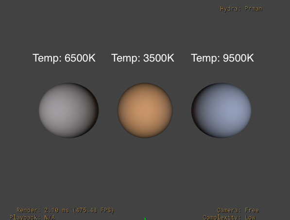
In the following example output, the lights have colorTemperature values of 6500, 3500, and 9500. Notice that the 3500 value results in a “warmer” color, whereas the 9500 value results in a cooler, more pronounced blue tint.
def Scope "Lights"
{
    def RectLight "LightIntensity1"
    {
        uniform bool collection:lightLink:includeRoot = 0
        rel collection:lightLink:includes = [
            </TestSpheres/Sphere1>
        ]

        float inputs:intensity = 20.0
        bool inputs:enableColorTemperature = true
        float inputs:colorTemperature = 6500
        double3 xformOp:translate = (-2.5, 5, 3)
        uniform token[] xformOpOrder = ["xformOp:translate"]
    }
    def RectLight "LightIntensity2"
    {
        uniform bool collection:lightLink:includeRoot = 0
        rel collection:lightLink:includes = [
            </TestSpheres/Sphere2>
        ]

        float inputs:intensity = 20.0
        bool inputs:enableColorTemperature = true
        float inputs:colorTemperature = 3500
        double3 xformOp:translate = (0, 5, 3)
        uniform token[] xformOpOrder = ["xformOp:translate"]
    }
    def RectLight "LightIntensity3"
    {
        uniform bool collection:lightLink:includeRoot = 0
        rel collection:lightLink:includes = [
            </TestSpheres/Sphere3>
        ]

        float inputs:intensity = 20.0
        bool inputs:enableColorTemperature = true
        float inputs:colorTemperature = 9500
        double3 xformOp:translate = (2.5, 5, 3)
        uniform token[] xformOpOrder = ["xformOp:translate"]
    }
}
normalize is used to control whether the area of the light itself affects the power of the light. By default, normalize is false, meaning that the light power is adjusted by the area (or angular size) of the light. If normalize is true, the power of the light remains constant regardless of light area.
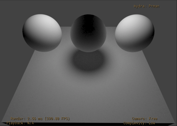
In the following example, two SphereLights are used to light two Spheres. The second SphereLight has an increased radius of 2, and normalize is false for both lights. The result is that the brightness of the second SphereLight is increased.
#usda 1.0
(
    upAxis = "Y"
)

def Scope "Lights"
{
    def SphereLight "Light1"
    {
        uniform bool collection:lightLink:includeRoot = 0
        rel collection:lightLink:includes = [
            </TestSpheres/Sphere1>
        ]

        float inputs:radius = 1
        bool inputs:normalize = false

        color3f inputs:color = (1, 1, 1)
        float inputs:intensity = 10.0
        double3 xformOp:translate = (-2.5, 5, 3)
        uniform token[] xformOpOrder = ["xformOp:translate"]
    }
    def SphereLight "Light2"
    {
        uniform bool collection:lightLink:includeRoot = 0
        rel collection:lightLink:includes = [
            </TestSpheres/Sphere2>
        ]

        float inputs:radius = 2
        bool inputs:normalize = false

        color3f inputs:color = (1, 1, 1)
        float inputs:intensity = 10.0
        double3 xformOp:translate = (0, 5, 3)
        uniform token[] xformOpOrder = ["xformOp:translate"]
    }
}

def Xform "TestSpheres"
{
    def Sphere "Sphere1"
    {
        color3f[] primvars:displayColor = [(1, 1, 1)] (
            interpolation = "constant"
        )
        double3 xformOp:translate = (-2.5, 5, -2)
        uniform token[] xformOpOrder = ["xformOp:translate"]
    }

    def Sphere "Sphere2"
    {
        color3f[] primvars:displayColor = [(1, 1, 1)] (
            interpolation = "constant"
        )
        double3 xformOp:translate = (0, 5, -2)
        uniform token[] xformOpOrder = ["xformOp:translate"]
    }
}
With normalize set to true for both lights, the same layer will look as follows.
The “area” for each of the intrinsic lights is calculated using a specific formula – see inputs:normalize for full details.
materialSyncMode controls how a light’s color interacts with any emissive material applied to the light prim. The different values are:
materialGlowTintsLight: All primary and secondary rays see the emissive/glow response as dictated by the bound Material while the base color seen by light rays (which is then modulated by all of the other LightAPI controls) is the multiplication of the color feeding the emission/glow input of the Material with the scalar or pattern input to color. This allows the light’s color to tint the geometry’s glow color while preserving access to intensity and other light controls as ways to further modulate the illumination.independent: All primary and secondary rays see the emissive/glow response as dictated by the bound Material, while the base color seen by light rays is determined solely by the light’s color value.noMaterialResponse: The geometry behaves as if there is no Material bound at all, i.e. there is no diffuse, specular, or transmissive response. The base color of light rays is entirely controlled by the the light’s color. This is the fallback value, except for MeshLights, where the fallback ismaterialGlowTintsLight.
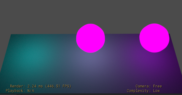
The following example has three (spherical) MeshLights with an emissive Glow Material applied to each. The Glow Material has an emissive color of magenta (1.0,0.0,1.0) and the light color value is cyan (0.0,1.0,1.0).
    #usda 1.0
    (
        upAxis = "Y"
    )

    # Emissive "glow" material
    def Scope "Looks"
    {
        def Material "Glow"
        {
            color3f inputs:color = (1,0,1) # magenta
            float inputs:glow_amount = 1
            token outputs:ri:surface.connect = </Looks/Glow/Surface.outputs:out>

            def Shader "Surface"
            {
                uniform token info:id = "PxrSurface"
                color3f inputs:diffuseColor.connect = </Looks/Glow.inputs:color>
                color3f inputs:glowColor.connect = </Looks/Glow.inputs:color>
                float inputs:glowGain.connect = </Looks/Glow.inputs:glow_amount>
                token outputs:out
            }
        }
    }

    # Floor and MeshLights
    def Xform "World"
    {
        def Mesh "Floor"
        {
            int[] faceVertexCounts = [4]
            int[] faceVertexIndices = [0,1,2,3]
            point3f[] points = [(-1,0,1),(1,0,1),(1,0,-1),(-1,0,-1)]
            uniform token subdivisionScheme = "none"
            float3 xformOp:scale = (6,1,6)
            uniform token[] xformOpOrder = ["xformOp:scale"]
        }

        def Mesh "MeshLightA"
        (
            prepend apiSchemas = [ "MaterialBindingAPI", "MeshLightAPI" ]
        )
        {
            # ...
            # points, faceVertexCounts, faceVertexIndices omitted for simplicity
            # ...
            token subdivisionScheme = "catmullClark"

            # LightAPI attributes
            float inputs:intensity = 1
            color3f inputs:color = (0, 1, 1) # cyan
            uniform token light:materialSyncMode = "independent"

            int inputs:ri:light:fixedSampleCount = 0

            float3 xformOp:translate = (0, 2, -4)
            uniform token[] xformOpOrder = ["xformOp:translate"]

            rel material:binding = </Looks/Glow>

            token info:implementationSource = "id"
        }

        def Mesh "MeshLightB"
        (
            references = </World/MeshLightA>
        )
        {
            uniform token light:materialSyncMode = "noMaterialResponse"
            float3 xformOp:translate = (-4,2,-4)
            uniform token[] xformOpOrder = ["xformOp:translate"]
        }
        def Mesh "MeshLightC"
        (
            references = </World/MeshLightA>
        )
        {
            uniform token light:materialSyncMode = "materialGlowTintsLight"
            float3 xformOp:translate = (4,2,-4)
            uniform token[] xformOpOrder = ["xformOp:translate"]
        }
    }
Rendered in RenderMan, the MeshLight with materialSyncMode set to “noMaterialResponse” emits a cyan color (from the light’s color value), the MeshLight with materialSyncMode set to “independent” has an additive result that approaches white, and the MeshLight with materialSyncMode set to “materialGlowTintsLight” has a tinted/multiplied result from the Material’s magenta emissive color.
See materialSyncMode for additional details on each of the different materialSyncMode values.
Light Shaping
The ShapingAPI schema configures and communicates light shaping settings, such as controlling light emission, light cone settings, and IES profiles. LightAPI does not automatically apply ShapingAPI, so you should apply the ShapingAPI schema to light prims that need these emission shaping settings.
Also, some renderers may not make use of all of these controls for all lights, e.g. for DistantLights, RenderMan will make use of shaping:focus, but not shaping:cone:angle.
Controlling Light Spread
Use shaping:focus and shaping:focusTint to control the emission (spread) of the light. For shaping:focus, higher values focus the light towards the center of the light focus, thereby narrowing the light spread. shaping:focusTint tints the emission in the light falloff region starting from the off-angle direction of the light towards the center.
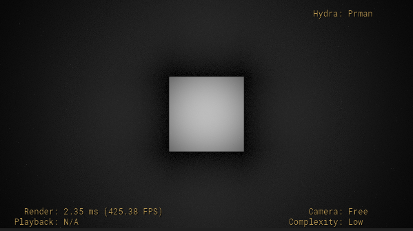
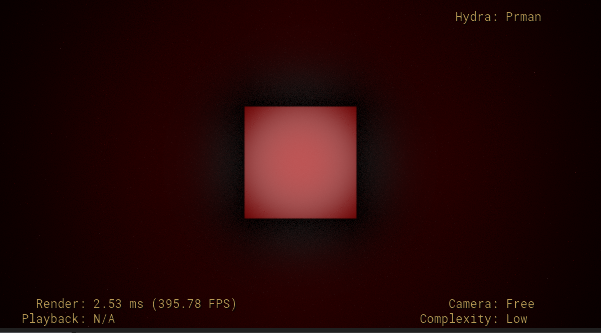
The following example uses a DiskLight over a Cube with a focus of 0.0 (off).
#usda 1.0
(
    upAxis = "Y"
)

def Scope "Lights"
{
    def DiskLight "Light1"
    (
        prepend apiSchemas = ["ShapingAPI"]
    )
    {
        float inputs:radius = 1

        float inputs:shaping:focus = 0

        double3 xformOp:translate = (0, 0, -11)
        uniform token[] xformOpOrder = ["xformOp:translate"]
    }
}

def Xform "TestGeom"
{
    def Cube "Cube1"
    {
        double size = 2
        color3f[] primvars:displayColor = [(1, 1, 1)] (
            interpolation = "constant"
        )
        double3 xformOp:translate = (0, 0, -13)
        uniform token[] xformOpOrder = ["xformOp:translate"]
    }

    def Plane "Plane"
    {
        color3f[] primvars:displayColor = [(1, 1, 1)] (
            interpolation = "constant"
        )
        double length = 20
        double width = 20
        double3 xformOp:translate = (0, 0, -14)
        uniform token[] xformOpOrder = ["xformOp:translate"]
    }
}
The light spread in RenderMan looks as follows.
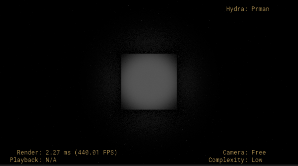
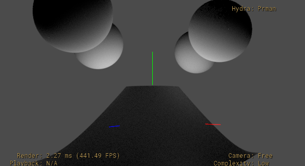
If we change the focus value to 20, we get the following.
Finally, if we use a focus value of 20 and a focusTint of red (1,0,0), we get the following.
See shaping:focusTint for the complete formula for how light emission is controlled by focus and focusTint.
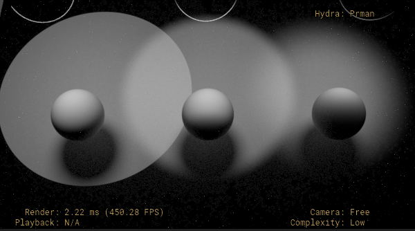
Configuring Light Cone and Spotlight Settings
Use shaping:cone:angle and shaping:cone:softness to have the light behave as a spotlight, with hard or soft edges. See shaping:cone:angle and shaping:cone:softness for the complete formula for how light emission is affected by these settings.
The following snippet sets up 3 SphereLights with a cone angle of 25, and cone softness values of 0 (hard edges), 0.25 (softer edges), and 0.75 (very soft edges).
def Scope "Lights"
{
    def SphereLight "Light1"
    (
        prepend apiSchemas = ["ShapingAPI"]
    )
    {
        uniform bool collection:lightLink:includeRoot = 0
        rel collection:lightLink:includes = [
            </TestGeom/Sphere1>,
            </TestGeom/Plane>
        ]

        float inputs:radius = 1
        color3f inputs:color = (1, 1, 1)
        float inputs:intensity = 10.0

        # The following provide a spotlight with hard edges
        float inputs:shaping:cone:angle = 25.0
        float inputs:shaping:cone:softness = 0

        double3 xformOp:translate = (-5, 2, -7)
        uniform token[] xformOpOrder = ["xformOp:translate"]
    }
    def SphereLight "Light2"
    (
        references = </Lights/Light1>
    )
    {
        uniform bool collection:lightLink:includeRoot = 0
        rel collection:lightLink:includes = [
            </TestGeom/Sphere2>,
            </TestGeom/Plane>
        ]

        # The following provide a spotlight with soft edges
        float inputs:shaping:cone:softness = 0.25
        double3 xformOp:translate = (0, 2, -7)
        uniform token[] xformOpOrder = ["xformOp:translate"]
    }
    def SphereLight "Light3"
    (
        references = </Lights/Light1>
    )
    {
        uniform bool collection:lightLink:includeRoot = 0
        rel collection:lightLink:includes = [
            </TestGeom/Sphere3>,
            </TestGeom/Plane>
        ]

        # The following provide a spotlight with softer edges
        float inputs:shaping:cone:softness = 0.75
        double3 xformOp:translate = (5, 2, -7)
        uniform token[] xformOpOrder = ["xformOp:translate"]
    }
}

def Xform "TestGeom"
{
    def Sphere "Sphere1"
    {
        color3f[] primvars:displayColor = [(1, 1, 1)] (
            interpolation = "constant"
        )
        double3 xformOp:translate = (-5, 0, -12)
        uniform token[] xformOpOrder = ["xformOp:translate"]
    }
    def Sphere "Sphere2"
    (
        references = </TestGeom/Sphere1>
    )
    {
        double3 xformOp:translate = (0, 0, -12)
        uniform token[] xformOpOrder = ["xformOp:translate"]
    }
    def Sphere "Sphere3"
    (
        references = </TestGeom/Sphere1>
    )
    {
        double3 xformOp:translate = (5, 0, -12)
        uniform token[] xformOpOrder = ["xformOp:translate"]
    }

    def Plane "Plane"
    {
        color3f[] primvars:displayColor = [(1, 1, 1)] (
            interpolation = "constant"
        )
        double length = 20
        double width = 20
        double3 xformOp:translate = (0, 0, -14)
        uniform token[] xformOpOrder = ["xformOp:translate"]
    }
}
Configuring Light Distribution Using IES Profiles
Use shaping:ies:file, shaping:ies:angleScale, and shaping:ies:normalize to control the distribution of light using an Illumination Engineering Society (IES) light profile file.
Use shaping:ies:file to set the IES asset to use (an .ies file target).
Use shaping:ies:angleScale to rescale the angular distribution of the IES profile – 0 indicates full coverage (no scaling), values less than 0 will effectively increase the size of the projected profile. See Best Practices When Working With angleScale below for additional best practices when using angleScale.
Set shaping:ies:normalize to true to prevent the IES profile amplitude from altering the energy of the light.
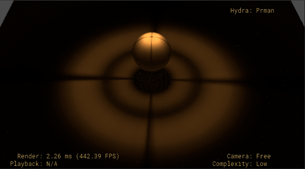
The following snippet uses a DiskLight using an “antique_street_lamp.ies” IES profile file, with an angularScale of 0.3, and normalize enabled.
def Scope "Lights"
{
    def DiskLight "Light1"
    (
        prepend apiSchemas = ["ShapingAPI"]
    )
    {
        float inputs:radius = 1

        float inputs:shaping:ies:angleScale = 0.3
        asset inputs:shaping:ies:file = @antique_street_lamp.ies@
        bool inputs:shaping:ies:normalize = 1

        float inputs:colorTemperature = 2500
        bool inputs:enableColorTemperature = 1

        double3 xformOp:translate = (0, 0, -6)
        uniform token[] xformOpOrder = ["xformOp:translate"]
    }
}
See shaping:ies:file, shaping:ies:angleScale, and shaping:ies:normalize for the complete formula for how light emission is affected by these settings. For details on the .ies file format, see the full specification, ANSI/IES LM-63-19
Best Practices When Working With angleScale
If you have an IES profile for a spotlight aimed “down”, use a positive shaping:ies:angleScale (> 0). Values for shaping:ies:angleScale between 0.0 and 1.0 will narrow the spotlight beam. Values for shaping:ies:angleScale greater than 1.0 will broaden the spotlight beam.
For example if the original IES profile is a downward spotlight with a total cone angle of 60°, then a shaping:ies:angleScale value of 0.5 will narrow it to have a cone angle of 30°, and a value of 1.5 will broaden it to have a cone angle of 90°.
If you have an IES profile for a spotlight aimed “up”, use a negative angleScale (< 0). Values between -1.0 and 0.0 will narrow the spotlight beam. Values less than -1.0 will broaden the spotlight beam.
For example, if the original IES profile is an upward spotlight with a total cone angle of 60°, then a shaping:ies:angleScale of -0.5 will narrow it to have a cone angle of 30°, and a value of -1.5 will broaden it to have a cone angle of 90°.
If you violate the above rules (i.e., use a negative angleScale for a spotlight aimed down), then authoring shaping:ies:angleScale will still alter the vertical-angle mapping, but in more non-intuitive ways (i.e., broadening / narrowing may seem inverted, and the IES profile may seem to “translate” through the vertical angles, rather than uniformly scale).
If you have an IES profile that isn’t clearly “aimed” in a single direction, or it’s aimed in a direction other than straight up or down, applying angleScale will alter the vertical angle mapping for your IES light, but it may be difficult to have a clear intuitive sense of how varying the angleScale will affect the shape of your light.
Shadows
The ShadowAPI schema configures and communicates shadow settings, such as shadow tinting and shadow falloff. LightAPI does not automatically apply ShadowAPI, so you should apply the ShadowAPI schema to light prims that need these shadow settings.
Note that ShadowAPI attributes are “non-physical” controls that ignore laws of physics when used in lighting calculations. These controls are useful for scenarios where you need additional artistic control over how shadows are rendered.
Enabling or Disabling Shadows
Use shadow:enable to enable or disable shadows created by the light prim the schema is applied to. By default this is enabled. If you need finer grain control where only certain objects in the scene should cast shadows, enable shadows and use the shadowLink collection via light-linking to specify which objects should cast shadows.
Changing Shadow Color
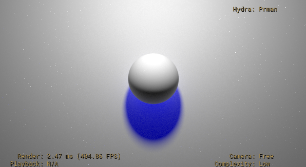
Use shadow:color to specify the tint of the shadow. This defaults to black. The following example sets shadow:color to blue on a SphereLight, resulting in a blue shadow cast from the Sphere.
#usda 1.0
(
    upAxis = "Y"
)

def Scope "Lights"
{
    def SphereLight "Light1"
    (
        prepend apiSchemas = ["ShadowAPI"]
    )
    {
        color3f inputs:shadow:color = (0, 0, 1)

        float inputs:exposure = 7
        double3 xformOp:translate = (0, 4, -8)
        uniform token[] xformOpOrder = ["xformOp:translate"]
    }
}

def Xform "TestGeom"
{
    def Sphere "Sphere"
    {
        color3f[] primvars:displayColor = [(1, 1, 1)] (
            interpolation = "constant"
        )
        double3 xformOp:translate = (0, 0, -13)
        uniform token[] xformOpOrder = ["xformOp:translate"]
    }

    def Plane "Plane"
    {
        color3f[] primvars:displayColor = [(1, 1, 1)] (
            interpolation = "constant"
        )
        double length = 20
        double width = 20
        double3 xformOp:translate = (0, 0, -14)
        uniform token[] xformOpOrder = ["xformOp:translate"]
    }
}
Adjusting Shadow Distance and Falloff
Use shadow:distance, shadow:falloff, and shadow:falloffGamma to adjust the overall shadow distance and falloff.
shadow:distance sets the maximum distance of the shadow, starting from the position of the point being shaded, measured between the occluder and the point. If this is set to -1 (the default), the maximum distance is effectively the distance from the shaded point to the light, so all occluders within that distance will cast shadows. This is often used to artificially reduce the distance shadows are cast.
shadow:falloff sets the size of the falloff zone, which is a region within the zone where the shadow will be rendered, where the shadow is rendered at full strength at the beginning of the falloff zone, and fades to no shadow at the maximum shadow distance.
shadow:falloffGamma is used to control the rate of the fade within the falloff zone, acting as an exponential gamma adjustment to the shadow strength based on the linear distance within the falloff zone.
The following simple example uses two DistantLights with different falloff settings. The first DistantLight has a falloff of 0, resulting in hard shadows. The second DistantLight uses a falloff of 1.5 to produce a softer shadow.
#usda 1.0
(
    upAxis = "Y"
)

def Scope "Lights"
{
    def DistantLight "Light1"
    (
        prepend apiSchemas = ["ShadowAPI"]
    )
    {
        uniform bool collection:shadowLink:includeRoot = 0
        rel collection:shadowLink:includes = [
            </TestSpheres/Sphere1>
        ]
        float inputs:intensity = 10000

        float inputs:shadow:distance = -1
        # No falloff zone, resulting in hard shadows
        float inputs:shadow:falloff = 0.0

        float3 xformOp:rotateXYZ = (25, 0, 0)
        uniform token[] xformOpOrder = ["xformOp:rotateXYZ"]
    }

    def DistantLight "Light2"
    (
        prepend apiSchemas = ["ShadowAPI"]
    )
    {
        uniform bool collection:shadowLink:includeRoot = 0
        rel collection:shadowLink:includes = [
            </TestSpheres/Sphere2>
        ]
        float inputs:intensity = 10000

        float inputs:shadow:distance = 4.5
        float inputs:shadow:falloff = 1.5

        float3 xformOp:rotateXYZ = (25, 0, 0)
        uniform token[] xformOpOrder = ["xformOp:rotateXYZ"]
    }
}

def Xform "TestSpheres"
{
    def Sphere "Sphere1"
    {
        color3f[] primvars:displayColor = [(1, 1, 1)] (
            interpolation = "constant"
        )
        double3 xformOp:translate = (-2, 0, -8)
        uniform token[] xformOpOrder = ["xformOp:translate"]
    }

    def Sphere "Sphere2"
    {
        color3f[] primvars:displayColor = [(1, 1, 1)] (
            interpolation = "constant"
        )
        double3 xformOp:translate = (2, 0, -8)
        uniform token[] xformOpOrder = ["xformOp:translate"]
    }

    def Plane "Plane"
    {
        color3f[] primvars:displayColor = [(1, 1, 1)] (
            interpolation = "constant"
        )
        double length = 20
        double width = 20
        double3 xformOp:translate = (0, 0, -12)
        uniform token[] xformOpOrder = ["xformOp:translate"]
    }
}
Mesh Lights
You might have scenarios where you need to use arbitrary shapes as light sources. Use cases include simulating things like neon signs, or having a deforming shape that also emits light.
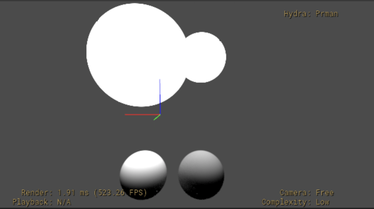
Use the MeshLightAPI schema to apply light behavior to a Mesh. Using this schema is preferred over applying LightAPI to a Mesh, as it applies commonly needed behavior, such as overriding the default materialSyncMode to “materialGlowTintsLight” to use the Mesh’s bound material. This schema also defaults shaderId to “MeshLight” to facilitate adding hooks for plugins to attach additional mesh light attributes.
VolumeLightAPI is a similar convenience schema, for USD Volumes that need to behave as lights.
The following example applies MeshLightAPI to a complex surface to act as a light for 4 spheres. The Mesh sits “below” the spheres.
#usda 1.0
(
    upAxis = "Y"
)

def Xform "MeshLight" (
)
{
    double xformOp:rotateX = -90
    #double3 xformOp:translate = (0, 10, 0)
    uniform token[] xformOpOrder = ["xformOp:rotateX", "xformOp:translate"]

    def Mesh "Mesh" (
        prepend apiSchemas = ["MeshLightAPI"]
    )
    {
        color3f inputs:color = (1, 1, 1)
        float inputs:intensity = 1.0

        # ...faceVertexCounts/Indices/points omitted for brevity...
    }
}

def Xform "TestSpheres"
{
    def Sphere "Sphere1"
    {
        color3f[] primvars:displayColor = [(1, 1, 1)] (
            interpolation = "constant"
        )
        double3 xformOp:translate = (-2.5, 3, 0)
        uniform token[] xformOpOrder = ["xformOp:translate"]
    }

    def Sphere "Sphere2"
    {
        color3f[] primvars:displayColor = [(1, 1, 1)] (
            interpolation = "constant"
        )
        double3 xformOp:translate = (0, 3, -4)
        uniform token[] xformOpOrder = ["xformOp:translate"]
    }

    def Sphere "Sphere3"
    {
        color3f[] primvars:displayColor = [(1, 1, 1)] (
            interpolation = "constant"
        )
        double3 xformOp:translate = (2.5, 3, 0)
        uniform token[] xformOpOrder = ["xformOp:translate"]
    }

    def Sphere "Sphere4"
    {
        color3f[] primvars:displayColor = [(1, 1, 1)] (
            interpolation = "constant"
        )
        double3 xformOp:translate = (0, 3, 4)
        uniform token[] xformOpOrder = ["xformOp:translate"]
    }

}
Note
If you are using Hydra and RenderMan for rendering, you will need to
enable scene indexes in Hydra (enabling USDIMAGINGGL_ENGINE_ENABLE_SCENE_INDEX
in your environment if needed) to see the results of mesh lights.
Light-linking and Shadow-linking
Lights can be linked to specific geometry prims. Linking lights with geometry lets you control light behavior associated with that geometry, such as whether the light illuminates that geometry, or if the geometry casts shadows for that light.
Lights are linked to geometry prims using collections. The LightAPI schema (and therefore all light schemas that inherit from LightAPI, such as all intrinsic lights) provides two collections, lightLink and shadowLink, to link prims for lighting calculations and shadow calculations respectively. Note that these collections have the collection’s includeRoot attribute set to true by default, which means that lights will illuminate and cast shadows for all objects. To illuminate or cast shadows for a specific set of prims, you can set the appropriate collection’s includeRoot attribute to false, and then set the collection’s includes relationship to specify which prims to include. Light-linking and shadow-linking also support usage of path expressions. To use this style of linking, set the includeRoot property to false and the collection’s membershipExpression to a path expression that matches the prims you want to include (see pattern-based collections for more details and examples on using path expressions in collections).
The following simple example has a single SphereLight, three Spheres, and a
“ground” Cube. Using the lightLink collection, the light has been configured
to only illuminate “Sphere1” and “Sphere3” (and “Ground”). Using the
shadowLink collection, the light has been configured to only cast shadows for
any prims that match the “/TestGeom/*2” path expression (which in this
example will only match </TestGeom/Sphere2>).
#usda 1.0
(
)

def Scope "Lights"
{
    def SphereLight "Light"
    {
        uniform bool collection:lightLink:includeRoot = 0
        rel collection:lightLink:includes = [
            </TestGeom/Sphere1>,
            </TestGeom/Sphere3>,
            </TestGeom/Ground>
        ]
        uniform bool collection:shadowLink:includeRoot = 0
        pathExpression collection:shadowLink:membershipExpression = "/TestGeom/*2"

        color3f inputs:color = (1, 1, 1)
        float inputs:radius = 1.0
        float inputs:intensity = 10.0

        double3 xformOp:translate = (0, 0, 2)
        uniform token[] xformOpOrder = ["xformOp:translate"]
    }
}

def Xform "TestGeom"
{
    def Sphere "Sphere1"
    {
        color3f[] primvars:displayColor = [(1, 1, 1)] (
            interpolation = "constant"
        )
        double3 xformOp:translate = (-2.5, 0, -2)
        uniform token[] xformOpOrder = ["xformOp:translate"]
    }

    def Sphere "Sphere2"
    {
        color3f[] primvars:displayColor = [(1, 1, 1)] (
            interpolation = "constant"
        )
        double3 xformOp:translate = (0, 0, -2)
        uniform token[] xformOpOrder = ["xformOp:translate"]
    }

    def Sphere "Sphere3"
    {
        color3f[] primvars:displayColor = [(1, 1, 1)] (
            interpolation = "constant"
        )
        double3 xformOp:translate = (2.5, 0, -2)
        uniform token[] xformOpOrder = ["xformOp:translate"]
    }

    def Cube "Ground"
    {
        color3f[] primvars:displayColor = [(1, 1, 1)] (
            interpolation = "constant"
        )
        double size = 8
        double3 xformOp:translate = (0, 0, -8)
        uniform token[] xformOpOrder = ["xformOp:translate"]
    }
}
See Collections and Patterns for more details and examples on working with USD collections.